Pumpkinator: Preparation Steps
These are the steps needed to prepare a kit before it's assembled. Preparation involves soldering and crimping, so it works best when done in batches across many kits at once. Each item below produces a finished part or sub-harness that gets plugged in later during Assembly Steps, which needs very few tools, if any.
-
Print the cases. 3D print the case, lid, and battery cradle for each kit. Printing takes the longest, so start here. The design is in Onshape.
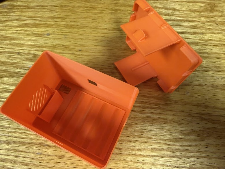
A printed case -
Solder header pins onto the Arduino and JQ6500 (if needed). Arduino Nano and JQ6500 boards sometimes ship with their pin headers unsoldered and loose in the bag rather than attached. If yours came this way, solder the header pins onto both boards so they can plug into a breadboard.
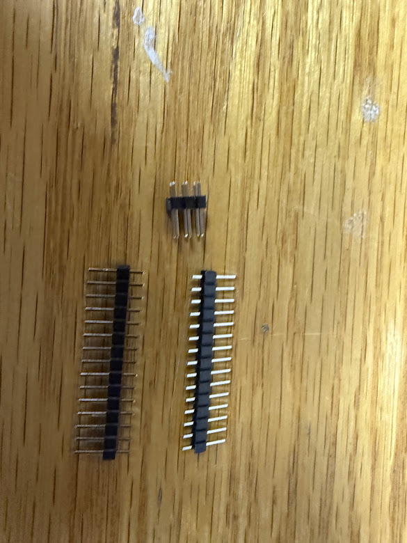
Loose header pins, as they come in the bag 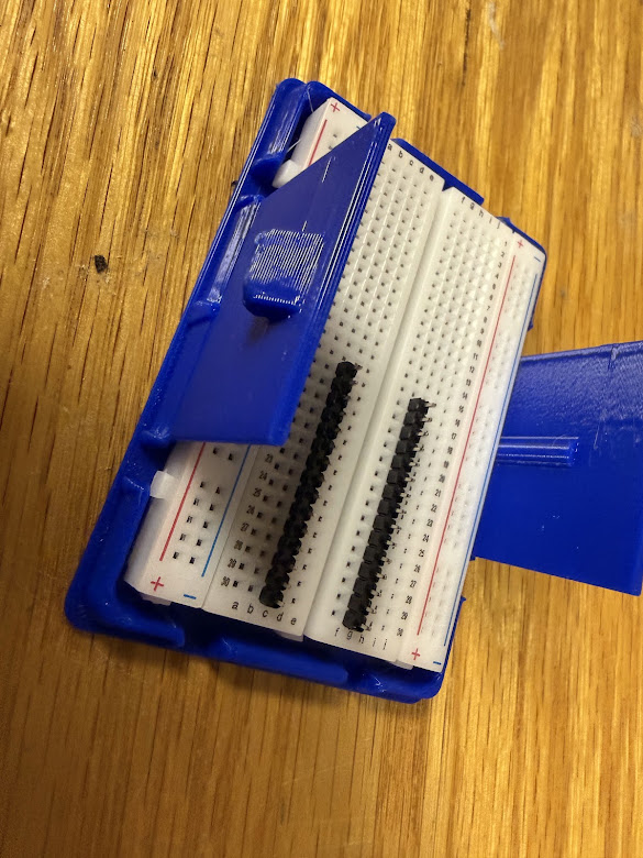
Header pins pushed into the breadboard 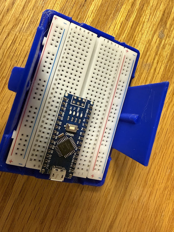
The Arduino Nano seated on the pins 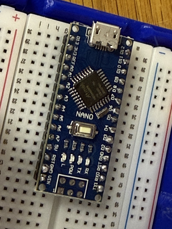
Close-up of the soldered pins -
Prep the power switch harness. Solder the red wire from the battery pack to one tab on the switch, then solder a second 6-inch length of red wire to the other tab on the switch — 6 inches works well for reaching from the switch to the breadboard. Tin the loose end of that second red wire with solder, and tin the end of the battery pack's black wire with solder. The result is a battery pack + switch unit with two tinned leads ready to plug into a breadboard.
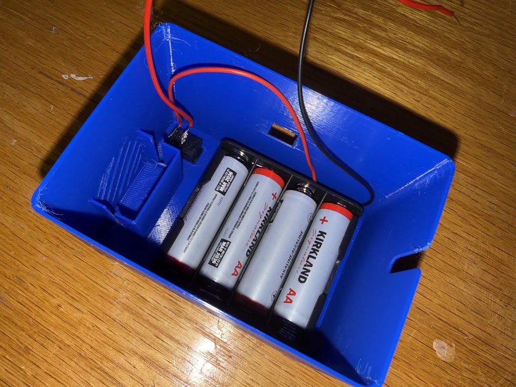
The battery pack and switch harness, sitting in the case -
Prep the LED wire harnesses. Cut 2 LEDs from a WS2812B strip. Solder 5-6 inches of wire to each LED: red for 5V, black for GND, and either green or white for the data/signal line (Din). 26-28 AWG wire works well.
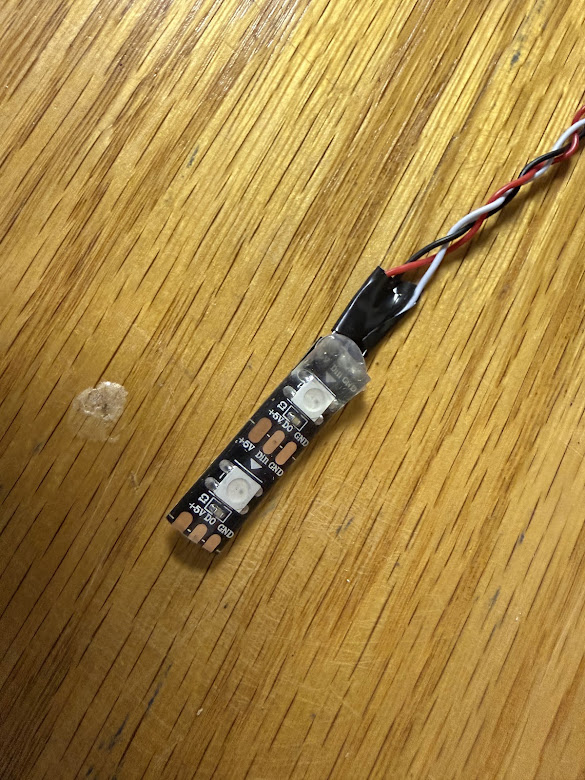
A finished LED harness: two LEDs with wires soldered on -
Prep the PIR sensor harness. Cut 3 strands of 26 AWG wire, about 20 inches each: black for ground, red for power, and a third color (yellow, blue, or green) for signal. Braid the 3 wires together to keep them from tangling. Crimp a connector onto one end of each wire and tin the other end with solder. Plug the crimped ends into the PIR sensor: with the sensor's dome facing up and the pin side facing you pointing down, the left pin is ground, the center pin is signal, and the right pin is power.
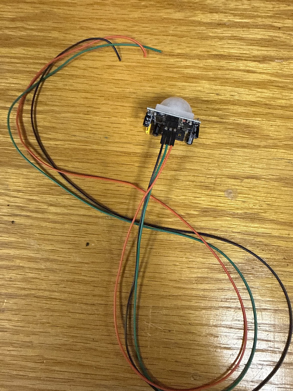
A finished PIR sensor harness -
Prep the speaker harness. Cut off the speaker's existing connector. Crimp a Molex male connector onto the black wire and another Molex male connector onto the red wire, then tape the two connectors together so they stay aligned as a pair.
-
Cut the sound card jumper wires. These connect the Arduino to the JQ6500 sound card. Solid core wire works well here since each one is a short breadboard-to-breadboard hop. Cut and strip four wires per kit:
- Power: a 2.5-inch red wire (Arduino 5V to the sound card).
- Ground: a 2-inch black or white wire (Arduino GND to the sound card).
- TX line: a 3-inch wire in any color other than red, black, or white (Arduino D2 to the sound card).
- RX line: a 2-inch wire in any color other than red, black, or white (from the resistor row to the sound card). Include a 1 kΩ resistor with each kit, since this line needs one.
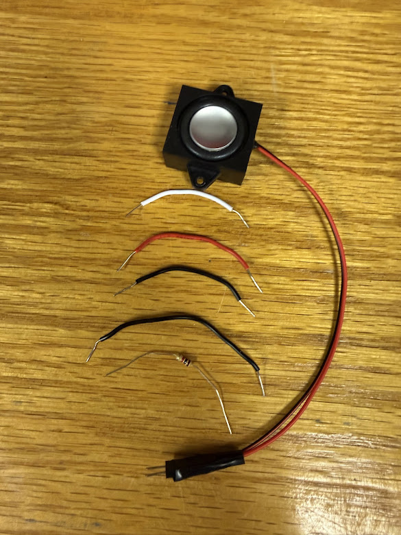
The speaker, along with the wires needed to connect the sound card to the Arduino
Once a batch of these is ready, hand them off along with the printed cases, breadboards, and remaining loose parts so students can complete the rest of the build in Assembly Steps.