Pumpkinator: Assembly Steps
Steps for assembling a kit that's already been through Preparation Steps — the case is printed and the harnesses (power switch, LEDs, PIR sensor, speaker, sound card jumpers) are already soldered and crimped, so this is the student-facing process for putting everything together. This page is a work in progress and will grow as steps are added. See the Overview for photos and pinouts of each component.
- Place the Arduino and JQ6500 on the breadboard. Position the Arduino Nano and the JQ6500 sound module on the breadboard.
- Glue the breadboard to the case. With the Arduino and JQ6500 in place, glue the breadboard onto the top of the 3D-printed case.
- Glue the battery box to the case. Glue the battery box to the bottom of the case.
As more components need 5V and GND, running every single one straight to the Arduino's pins gets crowded fast. In some cases it makes more sense to run one wire from the Arduino's 5V pin and one from a GND pin into the breadboard's side rails (the +/- columns along the edge), then connect each component to the rail instead of back to the Arduino directly. Two things to watch for: the left and right rails usually aren't connected to each other, so you may need a jumper wire bridging them if you need power on both sides; and keep VIN (the raw battery voltage, before the Nano's onboard regulator) on its own direct wire rather than sharing a rail with 5V-only components.
-
Load the code onto the Arduino. Follow How to update the code on the Arduino to install the Arduino IDE, connect the Arduino with a micro USB cable, and upload the Pumpkinator code.
-
Load the sounds onto the sound card. Follow How to load MP3s onto the sound card to copy the 10 sound effects onto the sound card in order. The method depends on whether your kit has an HW-896V2.0.2 or a true JQ6500, and that page covers both.
-
Wire and test the LEDs. Connect the red wire from the LED to the 5V pin on the Arduino. Connect the ground wire (black or white) to the GND pin on the Arduino. Connect the signal wire to D6 on the Arduino. To test: unplug the USB cable from the Arduino, close the Arduino IDE if it's open, then plug the USB cable back into the Arduino. Wait a few seconds — the LEDs should blink like a candle inside a pumpkin.
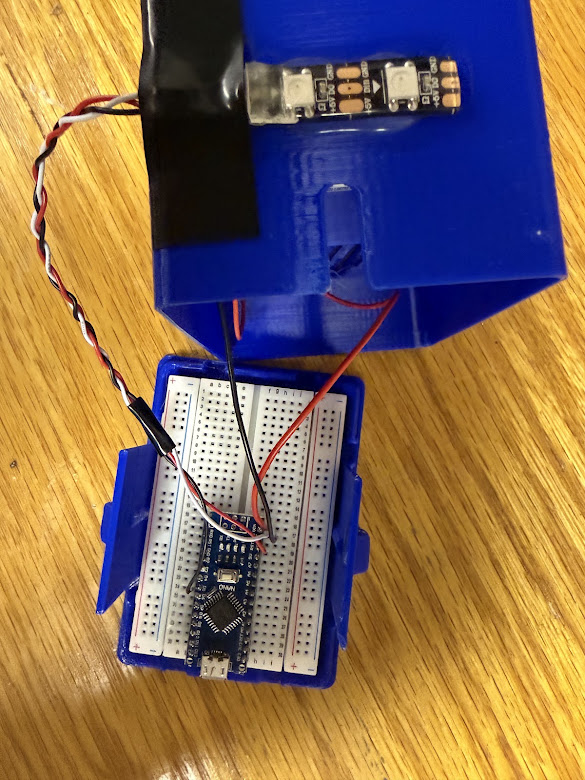
The LEDs wired to the Arduino -
Wire and test the PIR sensor. Unplug the USB cable from the Arduino before wiring. It's best to braid the PIR sensor's wires together so they tangle less. After braiding, connect the GND wire (black or white) to GND on the Arduino. Connect the red power wire to 5V on the Arduino. Connect the signal wire to D5 on the Arduino. To test: plug the USB cable back in and wait a few seconds for the LEDs to flicker like a candle. Wave your hand near the PIR sensor — it should detect the motion and change the LEDs to a disco light show. After the LEDs return to candle mode, wave your hand again and the lights should blink bright white. If you see that, it works!
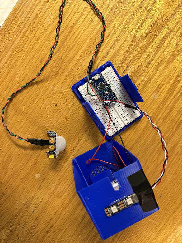
The PIR sensor wired to the Arduino -
Wire and test the sound card. Disconnect the USB cable first. The sound card's pins are numbered 1 to 8 along its left side, bottom to top, starting from the Mini USB end. Connect the short red jumper wire from Arduino 5V to pin 5 on the sound card. Connect the short white (or black) jumper wire from Arduino GND to pin 6 on the sound card. Connect the long green wire from D2 on the Arduino to pin 7 on the sound card. No resistor is needed on this line. Connect a 1 kΩ resistor from D3 on the Arduino to an empty row on the breadboard, then connect the short green wire from that same row to pin 8 on the sound card. To test: plug the USB cable back into the Arduino, wait for the candle flicker, then wave your hand by the PIR sensor to change the light show. When the LEDs change, you should see a red light on the sound board. If you do, that means the Arduino is sending the signal to the sound board to play a sound, and the power is connected correctly.
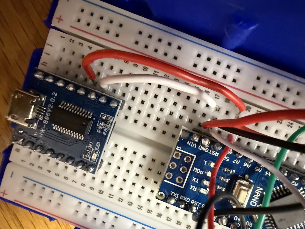
The sound card wired to the Arduino 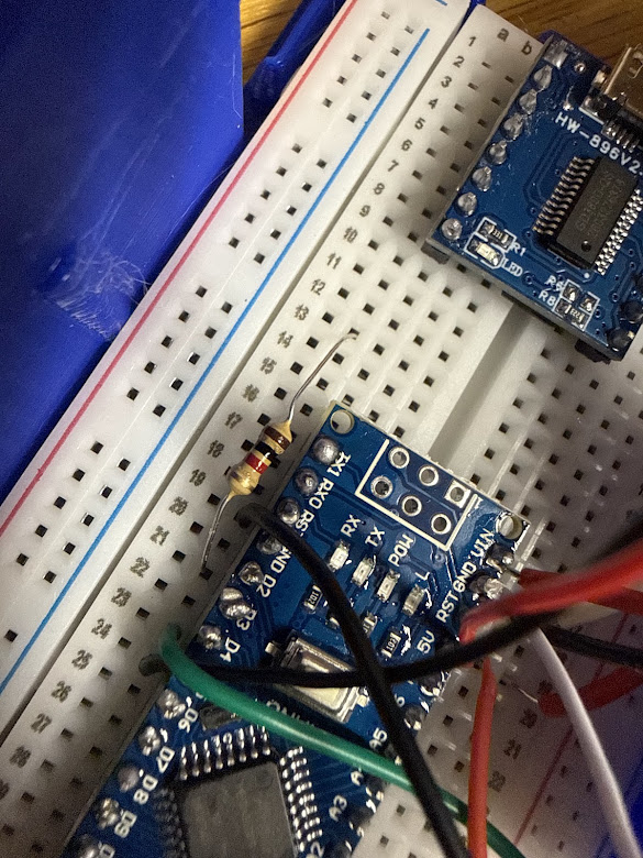
Close-up of the Arduino and sound card wiring 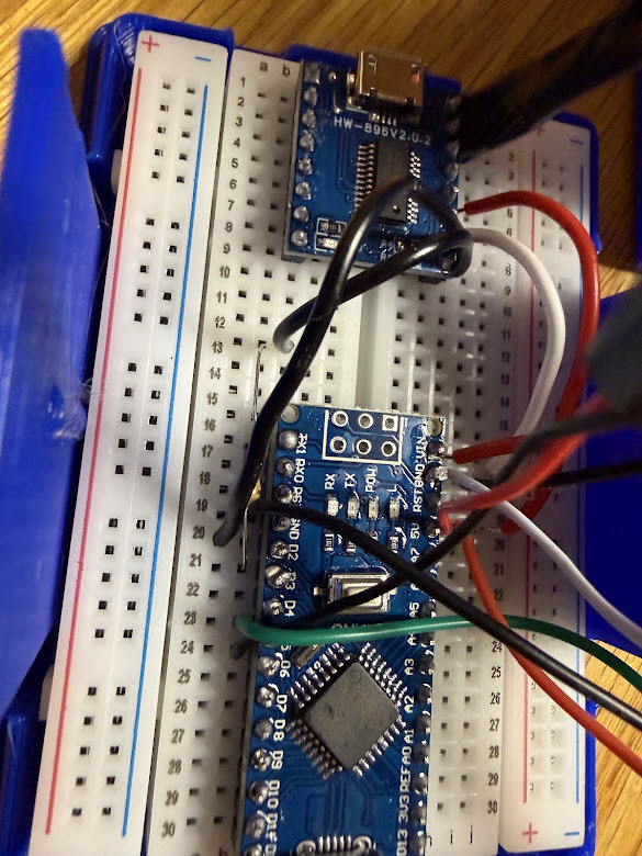
The full breadboard with the sound card connected -
Connect and test the speaker. Unplug the USB cable first. Plug the speaker into pin 1 (SPK+) and pin 2 (SPK-) on the sound card. Never let the speaker wires touch GND or VCC — this shorts the amplifier output and can damage the module. To test: plug the USB cable back in and repeat the same test as the previous step. This time you should hear the sound!
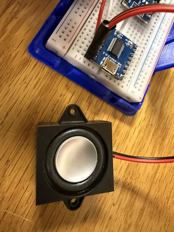
The speaker, ready to connect to the sound card -
Connect the battery and power on. Connect the red wire from the case to the VIN pin on the Arduino. Connect the black wire from the case to the Arduino GND pin. Put in 4 AA batteries, then turn on the switch.